
運放結合戰略上被放置的齊納二極管產生一個過程控制電路,電路有正、負向磁滯帶。
在需要間斷控制器的過程控制應用中,大多數初步選擇是兩個位置模型或開/關控制器。這種控制器的典型例子是空間加熱器。如果溫度低到設置點以下,加熱器打開,而如果溫度高過設置點,加熱器關閉。在模擬域,雙位置控制器的主要部分是模擬比較器或開環運算放大器。然而,為避免開關誤觸發,典型應用是使用熟知的Schmitt觸發器。
雙位置控制器模型的合理擴展是能夠提供若干個(多于兩個)控制器輸出的中間設定。使用這種間斷控制器模型減少雙位置模型固有的循環行為、超過目標或未達目標。然而實際上,雙位置模型不能達到滿意的時候,使用其它模型通常更快。最通用的例子是三位置控制器。圖1表示實現這種控制器的一個簡單方法。圖中,運算放大器周圍的Schmitt觸發器A1和A2分別實現負和正滯后。可以用模擬比較器,如LM311或相近的產品替代A1和A2。圖2顯示了圖1中電路的I/O轉換特性:
![]()
![]()
![]()
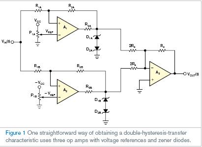

VZ 和VY分別為四個齊納二極管的擊穿和正向導通電壓。
圖3顯示了實現三位置控制器更有效的方法。電路基礎是單運算放大器,其不需要參考電壓。輸入和輸出二極管決定高于高壓和低于低壓的開關門限和比較器滯后。在中間帶放VIN(t)消除電路的輸入二極管,電路本質上是帶正反饋的電壓跟隨器。輸出電壓跟隨VA(t),但是正反饋確定VA(t),在輸出電壓的某些片斷設定這個電壓。所以,兩個約束確定電路狀態的輸出水平:VOUT(t)=VA(t), 和![]()
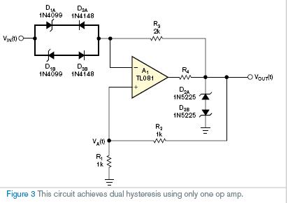
滿足這兩個約束的唯一條件是VOUT和VA=0V,所以當輸入二極管反向偏置時,輸出仍為0V。0V的輸出狀態持續到輸入電壓增加正或負值。然后,雙輸入齊納二極管的一個傳導,驅動放大器以輸入電壓±VH的正或負電壓輸出。在這個條件下,當絕對輸入電壓下降時,放大器在±VL的輸入電壓上輸出再次為0V。因此,VH 和VL的設計公式為![]()
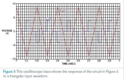
圖4顯示了電路用圖3值的I/O轉換特性,而D1A和D1B為6.8V 1N4099齊納二極管和D2A和D2B為3V 1N5225齊納二極管。圖5顯示當電路輸入采用三角波的輸出電壓。

英文原文:
Single op amp achieves double-hysteresis-transfer characteristic
An op amp combines with strategically placed zener diodes to yield a process-control circuit that has positive- and
negative-going hysteresis bands.
Herminio Martínez, Encarna García, and Juan Gámiz, Technical University of Catalonia, Barcelona, Spain; Edited by Charles H Small and Fran Granville -- EDN, 9/27/2007
In process-control applications requiring discontinuous controllers, the most elementary choice is a two-position-mode or on/off controller. A typical example of such a controller is a space heater. If the temperature drops below a setpoint, the heater turns on, and, if the temperature rises above the setpoint, it turns off. In the analog domain, the basis for the basic implementation of a two-position controller is an analog comparator or an open-loop operational amplifier. However, to avoid false switching, the typical implementation uses the well-known Schmitt trigger.
A logical extension of the two-position control mode is to provide several—rather than two—intermediate settings of the controller’s output. You can use this discontinuous-control mode to reduce the cycling behavior, overshoot, or undershoot inherent in the two-position mode. In fact, however, it is usually speedier to use some other mode when the two-position mode is unsatisfactory. The most common example is the three-position controller. Figure 1 shows one simple way to implement this controller. In this configuration, the Schmitt triggers around the operational amplifiers, A1 and A2
, which implement the negative and positive hysteresis, respectively. You can replace A1 and A2 with analog comparators, such as an LM311 or similar. Figure 2 shows the I/O-transfer characteristic of the circuit in Figure 1:
andVZ and VY are, respectively, the breakdown and the forward voltages of the four zener diodes.
Figure 3 shows a more efficient way to implement a three-position controller. The circuit’s basis is a single operational amplifier, and it needs no reference voltages. The input and output diodes determine the upper high-voltage and lower low-voltage switching-threshold levels and the hysteresis of the comparator. Putting VIN(t) in the middle band eliminates the input diodes from the circuit, and the circuit is essentially a voltage follower with positive feedback. The output voltage follows VA(t), but the positive feedback establishing VA(t) sets this voltage at some fraction of the output voltage. So, two constraints define the output level in this circuit state: VOUT(t)=VA(t), and
The only condition satisfying these two constraints is that VOUT and VA="0V"; so, the output remains at 0V when the input diodes are reverse-biased. A 0V output state continues until input voltage increases with positive or negative values. Then, one of the two input zener diodes conducts, driving the amplifier output positive or negative at an input voltage of ±VH. In this condition, when absolute input voltage decreases, the amplifier output again goes to 0V at an input voltage of ±VL. Thus, the design equations for VH and VL are VH="VZ1"+Vγ, and
Figure 4 shows the I/O-transfer characteristic of the circuit with the values in Figure 3, where D1A and D1B are 6.8V 1N4099 zener diodes and D2A and D2B are 3V 1N5225 zener diodes. Figure 5 shows the output voltage when you apply a triangular waveform at the circuit’s input.